

Seems like it's getting more and more common this, so I've decided to write a little guide about it as i am particularly bored right now... [O] Firstly, if you have any sort of problems then step 1 is always the same, diagnostics.
Step 1: using VAG COM log block 11 from 2000rpm to 4000rpm in 3rd gear on a flat straight bit of road
from this info in the log file, I can tell you everything about what the engine/turbo/ECU is doing. It means you can start diagnosing and faultfinding, it's no good posting up on the forum "help, my cars in limp mode when i floor it uphill, WTF do i do?" and then when somebody replies "probably the MAF mate" so then you go out and spend £80 odd quid on a new MAF (or however much these cost nowadays) and fit it on the off chance that it might fix the problem...
When you log block 11, you will end up with a whole bunch of numbers that look like this:
��
- which aren't much use like that, it makes it much clearer and easier to read if you convert it into a graph and then post the graph up. (btw... the above is not a really bad example, I have seen much worse attempts. some of which are just rows and rows of numbers with no headings![^o)] ) to make it clear and increase your chance of someone helping you you should make a graph and post that up, to make a graph here's what you need to do:
![Image]()
What do all the numbers mean??
- RPM is obviously the engine speed,
- Requested boost is how much boost the turbo should be making according to the map like in the ECU
- Actual boost is how much boost the turbo is making, measured by the MAP (Manifold Absolute Pressure) sensor. This should obviously be similar to the requested value, however it's normal for it to have a little bit of lag, and then spike as the turbo spools up before returning to "about the same as the requested value"
- N75 Duty Cycle this is given as a %, the highest it reads to is 94% and the lowest is around 30% but don't quote me on that. A low duty cycle equates to the ECU asking for more boost from the turbo, and a high duty cycle means the ECU has too much boost already and is requesting the boost be lower. so looking at the graph as accelerator is pressed, more fuel is injected and more boost is requested, as the boost is requested you will see the duty cycle go down, the boost will then rise to the required value as the turbo spools up and then the duty cycle will increase as you go up the revs. it does this because the amount of air flowing through the turbo is increasing, and with that increasing the need for the the vanes to close and build more boost is decreasing, hence the duty cycle rising.
*Note, for both of the boost readings they are in mBar and Absolute. Absolute means it's including atmospheric pressure which is normally around 1 Bar give or take a few millibars. so to get into a figure we work with (Bars of boost) you need to divide by 1000 and then subtract 1 Bar (If you happen to live at a great height from sea level then you should take this into account as the atmospheric pressure will be different)
** Another note, the figures you see in VAG COM also may not be all there is too it, because of limiters it will only show upto 2983.5 mBar, this is the limit of what VAG COM can read from a standard ECU. even if you were to fit and calibrate in a 4 bar MAP the actual boost would still never read above this even though the ECU is capable of measuring above it, it still doesn't let VAG COM show the real amount. the requested boost will also only show upto 2601 mBar for the same reason, and the only way to get around it is to edit the conversion factors in the ECU which sadly no tuners that I know of in the UK are able to do. I don't know how to do it, and this is all the other info I have about it if you are curious:
How a VNT turbo works:
- by using some adjustable vanes inside the turbine housing, it's possible to increase flow over the turbine wheel and speed it up at lower revs, this means it can spool up quicker than the traditional wastegate turbo. then once the engine speed is fast enough the vanes open up as there is now enough air moving through the turbo to spin the turbine fast enough without the need for the vanes to be closed. This video shows the vanes in action:
N75
![Image]()
it is basically a simple Y valve inside, the vacuum comes in at the top "vac in" and then depending on the duty cycle from the ECU it will either
Actuator
![Image]()
The actuator controls the VNT rod, which controls the VNT mechanism (the vanes) which ultimately determine the boost the turbo produces. It's moved one way by vacuum, and in the absence of any vacuum a spring will return it to it's resting position.
The Vacuum system
- on your TDI you might get confused faultfinding with the multitude of vacuum hoses you will see scattered around the bay. this is a simplified version of the vacuum system, it's exactly how it is on my car so if you have deleted your EGR and you are looking for a vacuum leak, it make sense to just rip everything out and pipe it like this, it will make it easier when you are faultfinding.
![Image]()
Common problems
- probably the most common is sticking vanes, also you could have incorrect VNT rod length, incorrectly setup stop screw or a vacuum leak/blockage.
- if the vanes are sticking then they are just going to jam in any position, normally fully closed, and then once the N75 cannot control the amount of boost (i.e if actual boost is not near enough to requested boost for a given amount of time) then it will go into limp mode.
- if there is a vacuum leak then there might not be sufficient vacuum in the line to pull the actuator down against the spring, move the VNT rod , close the vanes and generate boost, if this happens then after a certain amount of time (~2-3 sec) and still not enough actual boost then it will go into limp mode
- if the VNT rod is too short then it will effectively make the turbo far too sensitive and as soon as the ECU requests boost, before you know it you have twice the amount of boost requested as it suddenly spikes. once it does this, it's basically lost control of the boost and for some reason it won't go into limp mode, instead you will just feel a flat spot and if you have a boost gauge you will notice it going off the scale! the reason for the flat spot is the amount of EMP (exhaust manifold pressure) suddenly generated is too much to get though the turbine, so the engine is choked and held back. once the boost falls to a reasonable level you will feel the car start to pull again.
- if the VNT rod is too long it will mean the turbo is not responsive enough and it may feel sluggish and laggy.
Vacuum leak: if you have a vacuum leak then it will be the same as above, sluggish and laggy as the N75 will not be able to apply enough vacuum to the actuator.
Vacuum Blockage: one example of this is if the atmosphere line from the N75 is blocked then then it will have no way to vent the vacuum away from the actuator, and it will simply send 100% vacuum to the actuator at all times which will most probably end up in limp mode as the vanes will be jammed shut.
Checks and Procedures
How to check the Vacuum system:
- The most basic way to do this is remove the middle hose from the N75 and suck on it, you should be able to build up enough vacuum to move the VNT lever all the way to the stop screw. once there if you hold it for 1 minute and the lever does not move then all is working as it should be. if the VNT lever starts returning straight away, then there's a leak either in the vac pipe or the actuator diaphragm. if you have a vacuum pump you can use that to do this check, the vacuum will fall slightly on the gauge but as long as it's not rapidly descending it it ok.
http://cgi.ebay.co.uk/ws/eBayISAPI.dll?VISuperSize&item=230477698201
How to check the N75:
- perform an N75 output test using VAG COM and you should be able to see the actuator moving and hear the exhaust tone changing. alternatively you could swap the N75 for a working one to see if that changes the problem before buying a new one. N75's are very reliable, most of the time its something else causing the problem. also, if you remove the MAP sensor plug temporarily with the engine idling, you should hear a noticeable change in the exhaust note, then once you re-connect the MAP sensor plug it should go back to normal. this proves the N75 is "alive", however it doesn't mean it's 100% working as there could be another fault, sticking in low duty cycle position for example.
How to adjust the VNT rod length:
- When these turbos are new straight from Garrett, the rod length and stop screws are setup professionally in accordance with their specifications. since they do not publish these specifications a lot of re built, re manufactured, re furbished turbos do not have them properly set up. This includes so called "Garrett approved turbo re-builders" most of the time they will just leave them as standard and expect them to work, and they will work most of the time but obviously there is going to be times when they don't. And because the hybrid turbos are different specifications, the rod length and stop screw specifications from Garrett will no longer apply. this means the turbo must be set up either on a flow bench or on the car.
- Adjusting the rod length is necessary if you are getting erratic boost problems, if your duty cycle is above 80% at 4,000rpm then it needs made longer, and if your duty cycle is below 70% at 4,000rpm it needs made shorter. between 70-80% is ok, the closer to 80% the better.
How I do it is remove the TIP and get at it from above, it is possible to do it from below but there's limited space down there too, I prefer the top way. So once you have removed the tip, you will be able to see this -
![Image]()
I always remove the c-clip that holds the rod onto the vnt lever, it means you can push the rod off the lever as far is it will go right before it hits the compressor housing and you can then get your thumb in where the red square is to move the knurled ring and adjust the length. If it's a brand new turbo you might not need to do this because the rod will still be new and oiled, but on a 5 year old turbo they tend to be seized a bit, so this is why you need more room to get your whole thumb in there and get more purchase on the ring. To loosen the 10mm locknut, best way is to cut a 10mm spanner as shown:
![Image]()
If you try and use an open end, the jaws are too big to get onto the nut, so you need to cut a slot in the ring end, and also chop it in half because there's limited space between the bulkhead and the engine.
Here's a pic of the spanner in use and what you will see from above:
![Image]()
- adjustment should be done one turn at a time, and re check with VAG COM after adjustments.
How to cure sticking vanes:
- if the vanes are sticking, firstly you can try removing the actuator/VNT rod and giving the VNT lever a bloody good wiggle, it's not guaranteed to fix the problem but it worked for me years ago! To do this you need to gain access to the turbo either from above or below, remove the 2 X 10mm nuts holding the actuator to the mount, then remove the C-Clip holding the VNT rod onto the VNT lever, and then you can slide the rod off and remove the actuator altogether. once it's out of the way, give the VNT lever a good wiggle and then re-fit and see it it has cured the problem. if it doesn't work then you could either do a DIY refurb, you could send it away to a company to get it re-furbed, you could try using a boost valve, or you could attempt the Innotec VNT clean. more info on all of them below
Refurbish the Turbo:
- probably the most expensive way, most companies will charge about £250 to do this, maybe more. also be aware that it might come back with a new (incorrectly set up) actuator/VNT rod. you could also do the clean yourself if you are competent, here's a guide: http://pics.tdiclub.com/data/500/Drivbiwire_VNT_repair_procedure_small.pdf
Using a Boost Valve:
- here I have found a quote from myself about a year ago, this can work and help stop sticking vanes, however I would not use it for any other reason, i.e to stop spiking or mapping issues. I used one to stop spiking a year ago, it cured it a little bit but the problem was still there, albeit masked a little.
The reason it works is when the duty cycle is raised, the actuator sees less vacuum and the springing the actuator is expected to return the VNT lever back to open the vanes up. so it's not a force acting upon the actuator, but instead the absence of a force and it's all relying upon the spring. if the vanes are a little bit coked up, then it might stick or not respond as quickly as it should, so what this method does is put boost into the vacuum line, which has the opposite effect to the vacuum and will open the vanes up instantly, resulting in lower boost. It basically gives it a bit of a kick.
- I don't have personal experience of this, but I am told it works. more info on this thread http://uk-mkivs.net/forums/t/230403.aspx
Step 1: using VAG COM log block 11 from 2000rpm to 4000rpm in 3rd gear on a flat straight bit of road
from this info in the log file, I can tell you everything about what the engine/turbo/ECU is doing. It means you can start diagnosing and faultfinding, it's no good posting up on the forum "help, my cars in limp mode when i floor it uphill, WTF do i do?" and then when somebody replies "probably the MAF mate" so then you go out and spend £80 odd quid on a new MAF (or however much these cost nowadays) and fit it on the off chance that it might fix the problem...
When you log block 11, you will end up with a whole bunch of numbers that look like this:
��
| Group A: | '003 | Group B: | '011 | Group C: | |||||||
| Engine speed | MAF (specified) | MAF (actual) | EGR duty cycle | Engine speed | Spec. intake press. | Actual intake press. | D.cycle MAP | ||||
| TIME | 790-870 | 230-310 | 210-350 | 40-75% | TIME | 2850-3150 | 2200-2400 | 2100-2600 | 35-80% | TIME | |
| Marker | STAMP | RPM | mg/str | mg/str | % | STAMP | /min | mbar | mbar | % | STAMP |
| 0.4 | 2142 | 850 | 1068.2 | 4.8 | 0.01 | 2058 | 2325.6 | 2316.6 | 61.8 | ||
| 1.2 | 2289 | 850 | 1053.5 | 4.8 | 0.8 | 2205 | 2335.8 | 2328.3 | 63.8 | ||
| 2.03 | 2415 | 850 | 1048.6 | 4.8 | 1.62 | 2352 | 2346 | 2351.7 | 64.9 | ||
| 2.86 | 2562 | 850 | 1058.4 | 4.8 | 2.45 | 2478 | 2346 | 2351.7 | 64.9 | ||
| 3.68 | 2688 | 850 | 1058.4 | 4.8 | 3.28 | 2625 | 2346 | 2375.1 | 67.3 | ||
| 4.48 | 2814 | 850 | 1029 | 4.8 | 4.08 | 2751 | 2346 | 2375.1 | 67.3 | ||
| 5.28 | 2919 | 850 | 1014.3 | 4.8 | 4.88 | 2877 | 2346 | 2351.7 | 68.1 | ||
| 6.08 | 3045 | 850 | 1004.5 | 4.8 | 5.66 | 2982 | 2346 | 2340 | 67.3 | ||
| 6.88 | 3129 | 850 | 999.6 | 4.8 | 6.48 | 3087 | 2346 | 2340 | 67.3 | ||
| 7.68 | 3213 | 850 | 975.1 | 4.8 | 7.28 | 3171 | 2346 | 2351.7 | 68.5 | ||
| 8.48 | 3297 | 850 | 980 | 4.8 | 8.08 | 3255 | 2346 | 2328.3 | 67.7 | ||
| 9.28 | 3381 | 850 | 970.2 | 4.8 | 8.88 | 3339 | 2346 | 2351.7 | 68.5 | ||
| 10.06 | 3444 | 850 | 970.2 | 4.8 | 9.68 | 3423 | 2346 | 2363.4 | 69.7 | ||
| 10.88 | 3507 | 850 | 955.5 | 4.8 | 10.46 | 3486 | 2346 | 2351.7 | 70.1 | ||
| 11.68 | 3591 | 850 | 940.8 | 4.8 | 11.28 | 3549 | 2346 | 2351.7 | 70.1 | ||
| 12.48 | 3654 | 850 | 935.9 | 4.8 | 12.08 | 3612 | 2346 | 2340 | 69.7 | ||
| 13.28 | 3717 | 850 | 931 | 4.8 | 12.88 | 3675 | 2346 | 2363.4 | 70.9 | ||
| 14.09 | 3780 | 850 | 945.7 | 4.8 | 13.68 | 3738 | 2346 | 2375.1 | 72.1 | ||
| 14.92 | 3843 | 850 | 940.8 | 4.8 | 14.51 | 3801 | 2346 | 2386.8 | 74.1 |
- which aren't much use like that, it makes it much clearer and easier to read if you convert it into a graph and then post the graph up. (btw... the above is not a really bad example, I have seen much worse attempts. some of which are just rows and rows of numbers with no headings![^o)] ) to make it clear and increase your chance of someone helping you you should make a graph and post that up, to make a graph here's what you need to do:
A graph of block 11 will look like this:
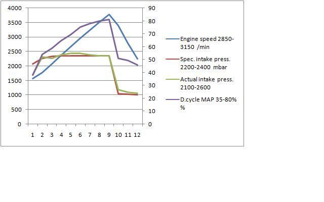
What do all the numbers mean??
- RPM is obviously the engine speed,
- Requested boost is how much boost the turbo should be making according to the map like in the ECU
- Actual boost is how much boost the turbo is making, measured by the MAP (Manifold Absolute Pressure) sensor. This should obviously be similar to the requested value, however it's normal for it to have a little bit of lag, and then spike as the turbo spools up before returning to "about the same as the requested value"
- N75 Duty Cycle this is given as a %, the highest it reads to is 94% and the lowest is around 30% but don't quote me on that. A low duty cycle equates to the ECU asking for more boost from the turbo, and a high duty cycle means the ECU has too much boost already and is requesting the boost be lower. so looking at the graph as accelerator is pressed, more fuel is injected and more boost is requested, as the boost is requested you will see the duty cycle go down, the boost will then rise to the required value as the turbo spools up and then the duty cycle will increase as you go up the revs. it does this because the amount of air flowing through the turbo is increasing, and with that increasing the need for the the vanes to close and build more boost is decreasing, hence the duty cycle rising.
*Note, for both of the boost readings they are in mBar and Absolute. Absolute means it's including atmospheric pressure which is normally around 1 Bar give or take a few millibars. so to get into a figure we work with (Bars of boost) you need to divide by 1000 and then subtract 1 Bar (If you happen to live at a great height from sea level then you should take this into account as the atmospheric pressure will be different)
** Another note, the figures you see in VAG COM also may not be all there is too it, because of limiters it will only show upto 2983.5 mBar, this is the limit of what VAG COM can read from a standard ECU. even if you were to fit and calibrate in a 4 bar MAP the actual boost would still never read above this even though the ECU is capable of measuring above it, it still doesn't let VAG COM show the real amount. the requested boost will also only show upto 2601 mBar for the same reason, and the only way to get around it is to edit the conversion factors in the ECU which sadly no tuners that I know of in the UK are able to do. I don't know how to do it, and this is all the other info I have about it if you are curious:
How the N75, Vacuum system, Actuator and VNT turbo work.so you have a 16 bit value of measued MAP, this comes from the 2D linearisation you fixed, then that value is muliplied by the 16 to 8 bit factor to convert the measued boost into 8bit 0x00 to 0xFF, then that value is sent to vagcom, the ecu also send the kwp1281 data so vagcom knows what formula it must multiply the 0x00 to 0xFF value to get the correct value and unit on the screen it's as simple as that![Image]()

How a VNT turbo works:
- by using some adjustable vanes inside the turbine housing, it's possible to increase flow over the turbine wheel and speed it up at lower revs, this means it can spool up quicker than the traditional wastegate turbo. then once the engine speed is fast enough the vanes open up as there is now enough air moving through the turbo to spin the turbine fast enough without the need for the vanes to be closed. This video shows the vanes in action:

it is basically a simple Y valve inside, the vacuum comes in at the top "vac in" and then depending on the duty cycle from the ECU it will either
- send all of the vacuum out of the "vac out" line to the actuator (low duty cycle, more boost requested)
- send all of the vac out to "atmosphere" (high duty cycle, less boost requested)
- or anywhere in between
Actuator

The actuator controls the VNT rod, which controls the VNT mechanism (the vanes) which ultimately determine the boost the turbo produces. It's moved one way by vacuum, and in the absence of any vacuum a spring will return it to it's resting position.
The Vacuum system
- on your TDI you might get confused faultfinding with the multitude of vacuum hoses you will see scattered around the bay. this is a simplified version of the vacuum system, it's exactly how it is on my car so if you have deleted your EGR and you are looking for a vacuum leak, it make sense to just rip everything out and pipe it like this, it will make it easier when you are faultfinding.

Common problems
- probably the most common is sticking vanes, also you could have incorrect VNT rod length, incorrectly setup stop screw or a vacuum leak/blockage.
- if the vanes are sticking then they are just going to jam in any position, normally fully closed, and then once the N75 cannot control the amount of boost (i.e if actual boost is not near enough to requested boost for a given amount of time) then it will go into limp mode.
- if there is a vacuum leak then there might not be sufficient vacuum in the line to pull the actuator down against the spring, move the VNT rod , close the vanes and generate boost, if this happens then after a certain amount of time (~2-3 sec) and still not enough actual boost then it will go into limp mode
- if the VNT rod is too short then it will effectively make the turbo far too sensitive and as soon as the ECU requests boost, before you know it you have twice the amount of boost requested as it suddenly spikes. once it does this, it's basically lost control of the boost and for some reason it won't go into limp mode, instead you will just feel a flat spot and if you have a boost gauge you will notice it going off the scale! the reason for the flat spot is the amount of EMP (exhaust manifold pressure) suddenly generated is too much to get though the turbine, so the engine is choked and held back. once the boost falls to a reasonable level you will feel the car start to pull again.
- if the VNT rod is too long it will mean the turbo is not responsive enough and it may feel sluggish and laggy.
Vacuum leak: if you have a vacuum leak then it will be the same as above, sluggish and laggy as the N75 will not be able to apply enough vacuum to the actuator.
Vacuum Blockage: one example of this is if the atmosphere line from the N75 is blocked then then it will have no way to vent the vacuum away from the actuator, and it will simply send 100% vacuum to the actuator at all times which will most probably end up in limp mode as the vanes will be jammed shut.
Checks and Procedures
How to check the Vacuum system:
- The most basic way to do this is remove the middle hose from the N75 and suck on it, you should be able to build up enough vacuum to move the VNT lever all the way to the stop screw. once there if you hold it for 1 minute and the lever does not move then all is working as it should be. if the VNT lever starts returning straight away, then there's a leak either in the vac pipe or the actuator diaphragm. if you have a vacuum pump you can use that to do this check, the vacuum will fall slightly on the gauge but as long as it's not rapidly descending it it ok.
http://cgi.ebay.co.uk/ws/eBayISAPI.dll?VISuperSize&item=230477698201
How to check the N75:
- perform an N75 output test using VAG COM and you should be able to see the actuator moving and hear the exhaust tone changing. alternatively you could swap the N75 for a working one to see if that changes the problem before buying a new one. N75's are very reliable, most of the time its something else causing the problem. also, if you remove the MAP sensor plug temporarily with the engine idling, you should hear a noticeable change in the exhaust note, then once you re-connect the MAP sensor plug it should go back to normal. this proves the N75 is "alive", however it doesn't mean it's 100% working as there could be another fault, sticking in low duty cycle position for example.
How to adjust the VNT rod length:
- When these turbos are new straight from Garrett, the rod length and stop screws are setup professionally in accordance with their specifications. since they do not publish these specifications a lot of re built, re manufactured, re furbished turbos do not have them properly set up. This includes so called "Garrett approved turbo re-builders" most of the time they will just leave them as standard and expect them to work, and they will work most of the time but obviously there is going to be times when they don't. And because the hybrid turbos are different specifications, the rod length and stop screw specifications from Garrett will no longer apply. this means the turbo must be set up either on a flow bench or on the car.
- Adjusting the rod length is necessary if you are getting erratic boost problems, if your duty cycle is above 80% at 4,000rpm then it needs made longer, and if your duty cycle is below 70% at 4,000rpm it needs made shorter. between 70-80% is ok, the closer to 80% the better.
How I do it is remove the TIP and get at it from above, it is possible to do it from below but there's limited space down there too, I prefer the top way. So once you have removed the tip, you will be able to see this -

I always remove the c-clip that holds the rod onto the vnt lever, it means you can push the rod off the lever as far is it will go right before it hits the compressor housing and you can then get your thumb in where the red square is to move the knurled ring and adjust the length. If it's a brand new turbo you might not need to do this because the rod will still be new and oiled, but on a 5 year old turbo they tend to be seized a bit, so this is why you need more room to get your whole thumb in there and get more purchase on the ring. To loosen the 10mm locknut, best way is to cut a 10mm spanner as shown:

If you try and use an open end, the jaws are too big to get onto the nut, so you need to cut a slot in the ring end, and also chop it in half because there's limited space between the bulkhead and the engine.
Here's a pic of the spanner in use and what you will see from above:

- adjustment should be done one turn at a time, and re check with VAG COM after adjustments.
How to cure sticking vanes:
- if the vanes are sticking, firstly you can try removing the actuator/VNT rod and giving the VNT lever a bloody good wiggle, it's not guaranteed to fix the problem but it worked for me years ago! To do this you need to gain access to the turbo either from above or below, remove the 2 X 10mm nuts holding the actuator to the mount, then remove the C-Clip holding the VNT rod onto the VNT lever, and then you can slide the rod off and remove the actuator altogether. once it's out of the way, give the VNT lever a good wiggle and then re-fit and see it it has cured the problem. if it doesn't work then you could either do a DIY refurb, you could send it away to a company to get it re-furbed, you could try using a boost valve, or you could attempt the Innotec VNT clean. more info on all of them below
Refurbish the Turbo:
- probably the most expensive way, most companies will charge about £250 to do this, maybe more. also be aware that it might come back with a new (incorrectly set up) actuator/VNT rod. you could also do the clean yourself if you are competent, here's a guide: http://pics.tdiclub.com/data/500/Drivbiwire_VNT_repair_procedure_small.pdf
Using a Boost Valve:
- here I have found a quote from myself about a year ago, this can work and help stop sticking vanes, however I would not use it for any other reason, i.e to stop spiking or mapping issues. I used one to stop spiking a year ago, it cured it a little bit but the problem was still there, albeit masked a little.
The reason it works is when the duty cycle is raised, the actuator sees less vacuum and the springing the actuator is expected to return the VNT lever back to open the vanes up. so it's not a force acting upon the actuator, but instead the absence of a force and it's all relying upon the spring. if the vanes are a little bit coked up, then it might stick or not respond as quickly as it should, so what this method does is put boost into the vacuum line, which has the opposite effect to the vacuum and will open the vanes up instantly, resulting in lower boost. It basically gives it a bit of a kick.
Innotec Turbo clean:right here is something else you can do to to try and stop sticking VNT vanes, a manual boost controller. set it to open at just above your max requested boost pressure (~1.6 bar for a mapped PD150)
so for example if we have a mapped 150, as soon as the charge pressure reaches 1.6 bar the MBC sends 1.6 bar of boost pressure down into the N75-actuator vacuum line and firmly seats the actuator in the "vanes open" position. the key thing here is boost into vacuum line! as long as the turbo is not rediculously coked up the extra force on the actuaor should be enough to keep them moving freely
![Image]()
![Image]()
the type of MBC you get is important too, do not get a bleed valve, you need a ball and spring type one. they are on ebay for £20-30 or if you want you can buy a shiny one from demon tweeks etc.., that has a click adjust setting with lockout, these are very easy to set up but are more expensive and effectively the same thing. do not buy a turbosmart boost tee, it will not work properly.
the one I bought had a small hole which needed blocking up, I used chemical metal but i'm sure any sort of glue would work. if you don't block it up it will act as a vacuum leak in the N75-actuator line.


- I don't have personal experience of this, but I am told it works. more info on this thread http://uk-mkivs.net/forums/t/230403.aspx
 ]
]